MLA-S (light QRP) v.2
- Home
- Magnetic loop antennas
- MLA-S (light QRP) v.2
MLA-S (light QRP) v.2
Advantages of MLA-SMART can be best described as „ small, light-weight, low-cost, wide-band.“ Max usable RF power input: 10W max on all bands. Operating SW Bands: 80m, 60m, 40m, 30m, 20m, 17m, 15m, 12m, 10m, CB. The loop does not need support with reinforcing cables. The antenna loop cannot be twisted to a small diameter. Tripod included, notebook bag not included.
Description
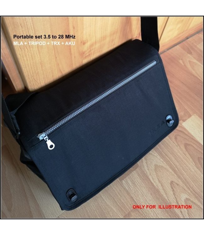
What can be fit in a notebook bag for /p activity. Notebook bag not included!
- 1 pc MLA-S (light QRP) 3,5 to 28 MHz inclusive support structure
- 1 pc TRX FT817 or X5105
- 1 pc TRIPOD
- 1 pc PB (aku) 40 Ah (144 Wh)
- 1 set of cables
MLA-S (light QRP), is portable magnetic loop antenna, it is a new product of the Czech BTV company which has continued in MLA development for years. This is the third commercial MLA version built using the concept of patented magnetic loop antennas known as MLA-SMART. The antennas in this category differ from the earlier versions by a more complex architecture of the basic L/C resonant circuit. Classical MLAs have one or more loop turns made of a metal pipe to which an external resonant capacitor is connected. In MLA-ER design (by OK2ER) the capacitor is made as a quasi-virtual capacitor created by inserting a metal pad into the loop pipe cavity. This antenna has not become too popular despite its simplicity, mostly due to its demanding tuning procedure. The concept of MLA-SMART design improves the MLA-ER idea, while its complicated tuning is avoided. As the loop inductance in MLA-SMART a multi-layer conductor is utilized in the L/C circuit, in which the second layer is used as the virtual capacitor of the L/C circuit. The third layer can optionally be used as a capacitive coupling section of the antenna loop.
Advantages of MLA-SMART can be best described as „small, light-weight, low-cost, wide-band.“
So far there were few magnetic loop antennas on the market which would be capable to operate over the full HF frequency range, or even on 160-m band. One of such antennas came also from the BTV design workshop, and was named MLA-M (multi-band). Over seven years, some 700 of these unique two-turn MLAs were sold. The new MLA-S (MMT), with an added value, can fully replace the MLA-M. Its advantage is that at the top of HF band segment, by avoiding the shorted second loop turn, MLA-S has its efficiency improved ten times (10-dB difference).
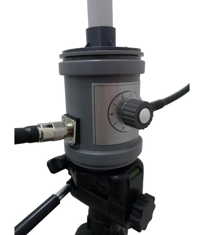
MLA-S (light QRP) antenna is manually tuned, and manually turned on a tripod. The standard 1/4“ thread in its box base fits to any robust camera tripod. See Fig.5. The patented design of MLA-SMART L/C circuit allows to switch the antenna to any of three short-wave segments by one jumper, Fig.2. Over any of these segments the antenna can be continually tuned by a classic variable capacitor, Fig.3.
The short-wave segments selectable by MLA-S jumper are:
- 80 and 60 meters,
- 40 meters,
- 30 through 10 meters, see Fig.2 a,b,c.
For a correct MLA operation, two basic conditions must be met : a sophisticated design (manufacturer's task), correct tuning (user's task). The correct tuning includes also a correct impedance matching to a feeder. Contrary to other antennas, the new MLA-S is provided with the „FCL match“ that allows to match the antenna with SWR close to 1:1. See Fig.4.
Without meeting the last condition the antenna cannot radiate effectively as the complete antenna system does not behave as a magnetic loop antenna but rather as a „coaxial antenna“ terminated into a mismatched „expensive L/C circuit“.
Many MLA manufacturers do not think about the second important condition, and their antennas cannot be perfectly matched. All BTV MLAs are provided with a configurable coupling devices, to optimize the radiation of the RF power from a transmitter. (Most often, by a rotatable FCL – Faraday Coupling Loop, or the „triangle match“.)
Operating SW Bands: 80m, 60m, 40m, 30m, 20m, 17m, 15m, 12m, 10m, CB
Usable RF power input: maximum 10W.
Download
Technical parameters
- Frequency range:3,5 to 28 MHz
- Input impedance:50 Ohm
- Typical Q:up to 250
- Maximum usable power:10 W
- Best achiavable SWR:1:1 max 1:1,2
- Input connector:BNC
- Dimensions:0,85 x 0,17 x 0,90 m
- Weight:1 kg
- Loop Diameter:850 mm
-v-2.jpg)

-v-2_1.jpg)

-v-2.jpg)

-v-2_1.jpg)
